Learn Robotics by Building a Line Follower Robot: A Beginner-Friendly Guide
Robotics is one of the most practical and engaging ways to learn electronics, programming, and automation. For beginners, choosing the right project is critical. A line follower robot is widely considered one of the best entry-level robotics projects because it is simple to understand yet powerful enough to teach fundamental concepts of autonomous systems.
This guide explains how to build a line follower robot using Arduino UNO in a structured and beginner-friendly way. It focuses not just on building the robot, but on understanding how and why each part works. By the end of this guide, you will have a strong foundation in robotics principles that can be applied to more advanced projects.
What Is a Line Follower Robot?

A line follower robot is an autonomous robot that follows a predefined path, usually a black line on a white surface or vice versa. The robot uses sensors to detect the contrast between the line and the background and adjusts its movement accordingly.
The robot continuously makes decisions based on sensor input. When the robot detects the line on one side, it turns in that direction to stay aligned with the path. This constant sensing and correction process makes the robot autonomous, meaning it can operate without human control once started.
This project introduces important robotics concepts such as sensing, decision-making, control logic, and actuation.
Why a Line Follower Robot Is Ideal for Beginners

The line follower robot is an excellent starting point for learning robotics for several reasons.
- simple and low-cost hardware setup.
- demonstrates fundamental robotics concepts like sensing and control.
- allows easy testing and debugging with immediately visible results.
By working on this project, beginners learn how sensors interact with microcontrollers, how motors are controlled using driver circuits, and how software logic influences physical movement. These skills form the backbone of robotics and embedded systems.
Components Required and Their Purpose

Understanding the role of each component is essential before assembling the robot.
The Arduino UNO acts as the brain of the robot. It receives input from sensors, processes the data, and sends commands to the motors. It is popular for beginners due to its simplicity and strong community support.
Infrared sensors are used to detect the line. These sensors work by emitting infrared light and measuring how much of it reflects. Light surfaces reflect more light, while dark surfaces reflect less.
DC motors are responsible for movement. Since motors require more current than Arduino can supply, a motor driver such as L293D or L298N is used. The motor driver acts as an interface between the Arduino and the motors.
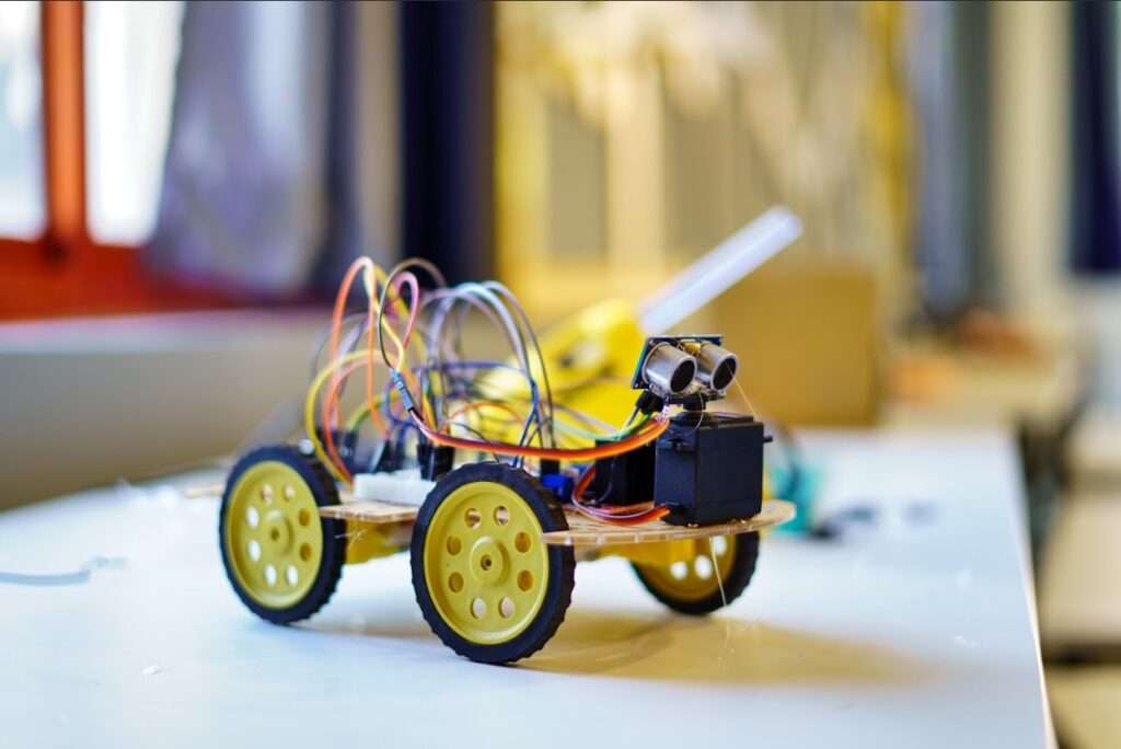
The chassis holds all components together. Wheels attached to motors allow motion, while a caster wheel helps maintain balance. A battery supplies power to the entire system.
Working Principle of the Line Follower Robot

The working principle of a line follower robot is based on light reflection. Infrared sensors placed at the bottom front of the robot continuously scan the surface beneath.
When the sensor is over a white surface, most of the infrared light is reflected, producing a high output signal. When the sensor is over a black line, less light is reflected, resulting in a low output signal.
The Arduino continuously reads the signals from the sensors and decides how the robot should move based on the detected surface. When both sensors detect white, the robot stays aligned with the path and moves forward. If the left sensor detects black while the right sensor remains on white, the robot turns left to return to the line. Similarly, if the right sensor detects black and the left sensor detects white, the robot turns right. When both sensors detect black, it indicates a junction or the end of the path, so the robot either slows down or stops based on the logic defined in the program.
This continuous feedback loop allows the robot to follow the line smoothly.
Circuit Design Overview

The circuit connects sensors, Arduino, motor driver, and motors into a complete system. The sensor outputs are connected to Arduino input pins, allowing the microcontroller to read surface information.
Arduino output pins are connected to the motor driver’s control pins. These signals determine the direction and speed of the motors. The motor driver outputs are connected directly to the motors.
Power management is important. The motors usually require higher voltage and current than the Arduino. Proper grounding and voltage regulation ensure stable operation and prevent damage to components.
Understanding the circuit rather than blindly following diagrams helps in debugging and future customisation.
Programming Logic and Control Flow
The software logic is what makes the robot intelligent. The Arduino program continuously reads the sensor values and makes decisions using conditional statements.
The core structure of the program involves reading digital or analogue values from sensors, comparing them against expected conditions, and controlling motor direction accordingly.
This project introduces beginners to control structures such as if-else statements, functions, and loop execution. These concepts are fundamental not only in robotics but in all areas of programming.
Uploading and modifying the code also teaches practical skills such as using the Arduino IDE, selecting the correct board and port, and debugging logical errors.
Testing and Calibration Process

After assembling the robot and uploading the code, testing is a critical step. The robot should be placed on a test track with a clear contrast between the line and the background.
Sensor calibration ensures reliable detection. Most infrared sensors include adjustable potentiometers that control sensitivity. These should be tuned so the sensor clearly distinguishes between black and white surfaces.
The height of the sensor from the ground also affects performance. Sensors placed too high may fail to detect the line, while sensors placed too low may give inconsistent readings.
Careful calibration significantly improves accuracy and stability.
Common Issues and Troubleshooting
Beginners may encounter problems such as incorrect movement, unstable turning, or complete failure to move. These issues often result from loose connections, low battery power, incorrect wiring, or improper sensor calibration.
Systematic troubleshooting involves checking one component at a time, verifying sensor outputs, ensuring motor driver enable pins are active, and confirming correct motor polarity.
Learning to troubleshoot builds confidence and reinforces understanding of how the system works.
Expanding the Project Further
Once the basic line follower works, the project can be expanded in many ways. More sensors can be added for better accuracy. Speed control can be implemented using pulse-width modulation. Advanced control algorithms, such as PID control, can be introduced for smoother movement.
Obstacle detection, wireless control, or display modules can also be integrated, transforming the basic robot into a more intelligent autonomous system.
Conclusion
Building a line follower robot using Arduino UNO is an excellent way to begin learning robotics. It provides a balance between simplicity and practical learning, covering essential concepts such as sensing, control logic, electronics, and embedded programming.
This project not only teaches how robots work but also develops problem-solving skills and logical thinking. With a solid understanding of this foundation, learners can confidently move on to more advanced robotics and automation projects.