
Overview
This project deals with a 2-road crossing traffic light. These lights work the same as our traffic system works here resistors are used so that no extra current is given to the LEDs as the extra current can damage them.
In this traffic light signal when signal 1 is red signal 2 will be green and vice versa.
Hardware required
- Arduino Uno R3
- LED
- Resistor
- Jumper Wires
Schematic Diagram
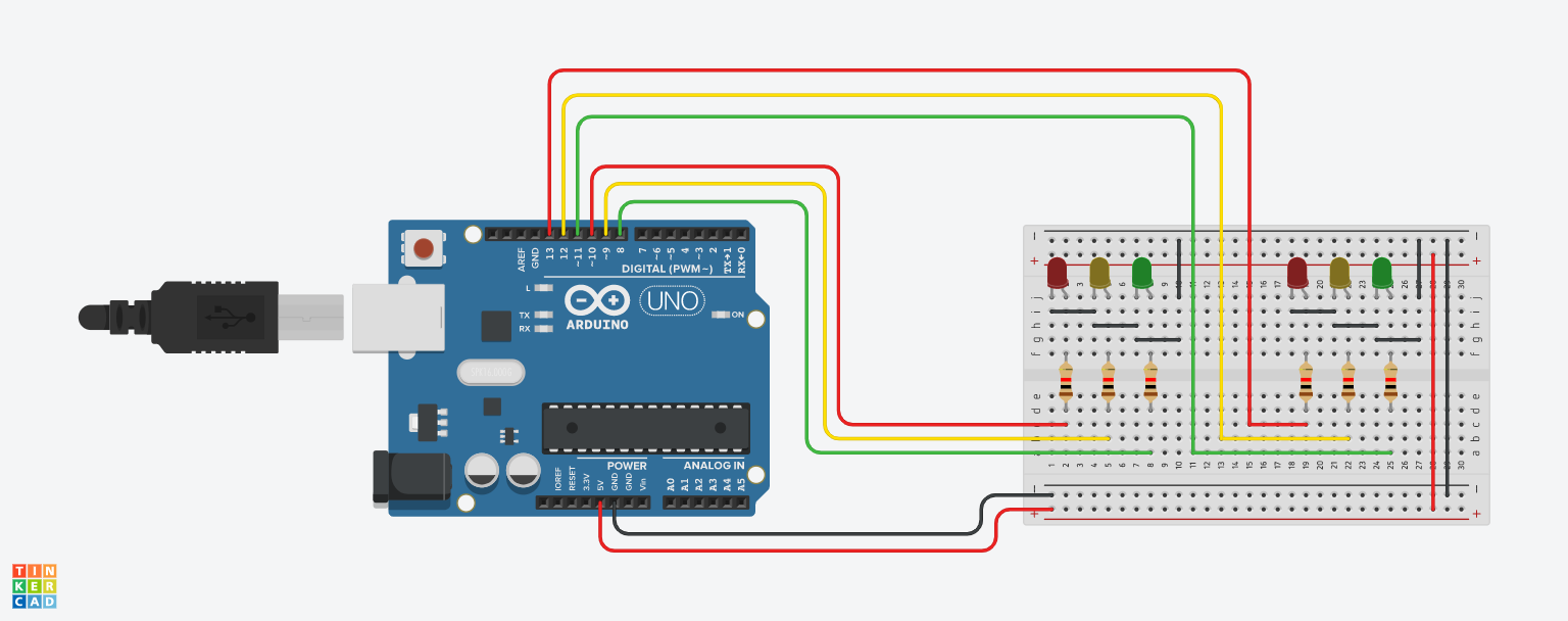
Fig 1. Circuit Diagram
Arduino Code :
// light one
int red1 = 10;
int yellow1 = 9;
int green1 = 8;

// light two
int red2 = 13;
int yellow2 = 12;
int green2 = 11;

void setup(){
    // light one
    pinMode(red1, OUTPUT);
    pinMode(yellow1, OUTPUT);
    pinMode(green1, OUTPUT);

    // light two
    pinMode(red2, OUTPUT);
    pinMode(yellow2, OUTPUT);
    pinMode(green2, OUTPUT);
}

void loop(){
    changeLights();
    delay(15000);
}

void changeLights(){
    // turn both yellows on
    digitalWrite(green1, LOW);
    digitalWrite(yellow1, HIGH);
    digitalWrite(yellow2, HIGH);
    delay(5000);

    // turn both yellows off, and opposite green and red
    digitalWrite(yellow1, LOW);
    digitalWrite(red1, HIGH);
    digitalWrite(yellow2, LOW);
    digitalWrite(red2, LOW);
    digitalWrite(green2, HIGH);
    delay(5000);

    // both yellows on again
    digitalWrite(yellow1, HIGH);
    digitalWrite(yellow2, HIGH);
    digitalWrite(green2, LOW);
    delay(3000);

    // turn both yellows off, and opposite green and red
    digitalWrite(green1, HIGH);
    digitalWrite(yellow1, LOW);
    digitalWrite(red1, LOW);
    digitalWrite(yellow2, LOW);
    digitalWrite(red2, HIGH);
    delay(5000);
}
Precautions
- Connections should be done properly.
- Arduino is case Sensitive so code accordingly.
- Give different and appropriate colors to the wires.